Q6 Specifications
| Revision as of 07:38, 3 February 2007 (edit) Paul (Talk | contribs) ← Previous diff |
Current revision (07:01, 25 November 2011) (edit) Paul (Talk | contribs) |
||
| Line 1: | Line 1: | ||
| + | ==Block Diagram== | ||
| + | {{SideMenuQ6}} | ||
| <BR> | <BR> | ||
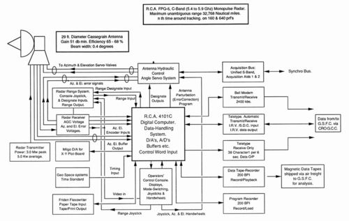
| - | {{}} | + | [[Image:Q6-block.jpg|left|thumbnail|500px|Note the RCA computer at the heart of the system: Block diagram reconstructed by Bob Hocking]] |
| - | [[Image:Q6-control.jpg|left|thumbnail|400px|FPQ-6 Control console. Seated unknown RCA engineers?; standing foreground Ron Burgess with Geoge Allan in front of him operating the controls, then to the right Len Algate, Q6 Engineer, hidden behind him Monte Sala, and at the back Mike Marsh: Photo – George Allan]] | + | |
| + | <BR><BR><BR><BR><BR><BR><BR><BR><BR><BR><BR><BR><BR><BR><BR><BR><BR><BR><BR><BR><BR><BR><BR> | ||
| ==Brief System Details== | ==Brief System Details== | ||
| - | <BR> | + | |
| <table x:str border=0 cellpadding=0 cellspacing=0 width=910 style='border-collapse: | <table x:str border=0 cellpadding=0 cellspacing=0 width=910 style='border-collapse: | ||
| collapse;table-layout:fixed;width:683pt'> | collapse;table-layout:fixed;width:683pt'> | ||
| Line 354: | Line 356: | ||
| </table> | </table> | ||
| - | =='Block Diagram' with 'Brief System Details' below== | + | |
| - | [[Image:Q6-block.jpg|left|thumbnail|700px|Note the RCA computer at the heart of the system]] | + | [[#top]] |
| + | <BR> | ||
Current revision
[edit]
Block Diagram
- Antenna structure
- Tracking and Ranging
- Brief system details
- RCA Computer
- Key Q6 Mission Activity
- Research activity
- BDA, CRO & RCA: Q6 partners
- Other Q-6 tales
Back to Station Equipment
[edit]
Brief System Details
| Antenna: | 29 ft Cassegrain feed, Gain - 51 db across the band. | ||||
| Feed: Five horn monopulse | |||||
| Depth of Null: 35 db | |||||
| Bandwidth: 0.4 degree. | |||||
| Polarisation: Transmit and receive vertical … | |||||
| … or Transmit left hand circular Receive right hand circular | |||||
| Rates: 500 mil/second. (both Azimuth and Elevation) | |||||
| Would track smoothly at 0.01mils/sec. (1 degree = 17.8 mils) | |||||
| Drive: Hydraulic, Azimuth bearing is hydrostatic. | |||||
| Rotation: Azimuth 360 degrees continuous. | |||||
| Elevation: -2 to +182 degrees. | |||||
| Receiver: | Three channel amplitude monopulse. | ||||
| Dynamic Range: 120 db. | |||||
| Threshold: Paramps on, 0.6 Mhz I.F. bandwidth, -112 dbm | . | ||||
| Preamplifier: Heated parametric amplifier (one per channel) Gain 17 db, bandwidth 100 khz. | |||||
| Noise Figure: Paramps on: 4 db. Paramps off: 10 db. | |||||
| I.F.: 30 Mhz | |||||
| I.F. Bandwidth: 4.8, 2.4, 1.6 or 0.6 Mhz | |||||
| Transmitter: | Power (pulse): 3.00 Megawatts, (average): 5.00 kilowatts | ||||
| Duty cycle: 0.00167 max. | |||||
| Pulse width: 0.25, 0.5, 1.0 or 2.4 microseconds | |||||
| Pulse Rep. Freq.: 150 or 640 p.p.s. normal (range from 142 to 1707 p.p.s. available) | |||||
| Frequency: 5.4 to 5.9 GHz. Variable in 243-KHz steps. | |||||
| Power Amplifier: Three-cavity klystron, gain about 30 db. | |||||
| Range System: | Digital, split gate auto track. | ||||
| Range: 600 yards to 32,768 nautical miles. unambiguous. | |||||
| Rates: Slew rate 240,000 yards/second maximum. | |||||
| Tracking rate: 20,000 yd/sec | |||||
| Target acceleration: 600 yards/sec/sec. | |||||
| Accuracy: Skin mode 5 yds Beacon mode 10 yards | |||||
| Angle System: | Rates: As for antenna | ||||
| Accuracy: 0.1 mil (S/N greater than 20 db) | |||||
| Scans: Rectangular, raster, circle or spiral. | |||||
| Max scan ampl: 2.8 degrees | |||||
| Major axis of rectangular or raster scans selectable | |||||
| Direction of rotation of circle and spiral selectable. | |||||
| Servo bandwidth: 5Hz. | |||||
| Data Ouput: | Range, Azimuth and Elevation at 0.1 second intervals. | ||||
| To data recorder (magnetic tape 200 bits per inch) … | |||||
| … and high speed modem (2400 bits per second). | |||||
| Range, Azimuth and Elevation at 6 second intervals. | |||||
| Low speed via teleprinter. (one line per 6 seconds) | |||||
| Displays: | 1 x 7 inch A scope. | ||||
| 1 x 5 inch A scope. | |||||
| 1 x 12 inch C scope. | |||||

