Q6 Specifications
| Revision as of 03:47, 15 August 2011 (edit) Paul (Talk | contribs) ← Previous diff |
Current revision (07:01, 25 November 2011) (edit) Paul (Talk | contribs) |
||
| Line 1: | Line 1: | ||
| ==Block Diagram== | ==Block Diagram== | ||
| - | [[Image:Q6-block.jpg|left|thumbnail|700px|Note the RCA computer at the heart of the system:                         Block diagram reconstructed by Bob Hocking]] | + | {{SideMenuQ6}} |
| - | [[#top]] | + | |
| <BR> | <BR> | ||
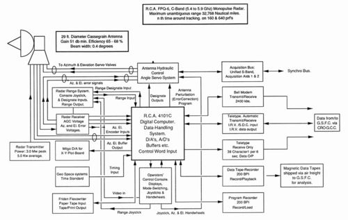
| - | {{SideMenuBackToQ6}} | + | [[Image:Q6-block.jpg|left|thumbnail|500px|Note the RCA computer at the heart of the system: Block diagram reconstructed by Bob Hocking]] |
| - | <br><br><br> | + | |
| - | <br><br><br> | + | <BR><BR><BR><BR><BR><BR><BR><BR><BR><BR><BR><BR><BR><BR><BR><BR><BR><BR><BR><BR><BR><BR><BR> |
| - | <br><br><br> | + | |
| - | <br><br><br> | + | |
| - | <br><br><br> | + | |
| - | <br><br><br> | + | |
| - | <br><br><br> | + | |
| - | <br><br><br> | + | |
| - | <br><br><br><br><br> | + | |
| - | : | + | |
| ==Brief System Details== | ==Brief System Details== | ||
| - | <BR> | + | |
| <table x:str border=0 cellpadding=0 cellspacing=0 width=910 style='border-collapse: | <table x:str border=0 cellpadding=0 cellspacing=0 width=910 style='border-collapse: | ||
| collapse;table-layout:fixed;width:683pt'> | collapse;table-layout:fixed;width:683pt'> | ||
| Line 364: | Line 355: | ||
| </tr> | </tr> | ||
| </table> | </table> | ||
| + | |||
| [[#top]] | [[#top]] | ||
| <BR> | <BR> | ||
Current revision
[edit]
Block Diagram
- Antenna structure
- Tracking and Ranging
- Brief system details
- RCA Computer
- Key Q6 Mission Activity
- Research activity
- BDA, CRO & RCA: Q6 partners
- Other Q-6 tales
Back to Station Equipment
[edit]
Brief System Details
| Antenna: | 29 ft Cassegrain feed, Gain - 51 db across the band. | ||||
| Feed: Five horn monopulse | |||||
| Depth of Null: 35 db | |||||
| Bandwidth: 0.4 degree. | |||||
| Polarisation: Transmit and receive vertical … | |||||
| … or Transmit left hand circular Receive right hand circular | |||||
| Rates: 500 mil/second. (both Azimuth and Elevation) | |||||
| Would track smoothly at 0.01mils/sec. (1 degree = 17.8 mils) | |||||
| Drive: Hydraulic, Azimuth bearing is hydrostatic. | |||||
| Rotation: Azimuth 360 degrees continuous. | |||||
| Elevation: -2 to +182 degrees. | |||||
| Receiver: | Three channel amplitude monopulse. | ||||
| Dynamic Range: 120 db. | |||||
| Threshold: Paramps on, 0.6 Mhz I.F. bandwidth, -112 dbm | . | ||||
| Preamplifier: Heated parametric amplifier (one per channel) Gain 17 db, bandwidth 100 khz. | |||||
| Noise Figure: Paramps on: 4 db. Paramps off: 10 db. | |||||
| I.F.: 30 Mhz | |||||
| I.F. Bandwidth: 4.8, 2.4, 1.6 or 0.6 Mhz | |||||
| Transmitter: | Power (pulse): 3.00 Megawatts, (average): 5.00 kilowatts | ||||
| Duty cycle: 0.00167 max. | |||||
| Pulse width: 0.25, 0.5, 1.0 or 2.4 microseconds | |||||
| Pulse Rep. Freq.: 150 or 640 p.p.s. normal (range from 142 to 1707 p.p.s. available) | |||||
| Frequency: 5.4 to 5.9 GHz. Variable in 243-KHz steps. | |||||
| Power Amplifier: Three-cavity klystron, gain about 30 db. | |||||
| Range System: | Digital, split gate auto track. | ||||
| Range: 600 yards to 32,768 nautical miles. unambiguous. | |||||
| Rates: Slew rate 240,000 yards/second maximum. | |||||
| Tracking rate: 20,000 yd/sec | |||||
| Target acceleration: 600 yards/sec/sec. | |||||
| Accuracy: Skin mode 5 yds Beacon mode 10 yards | |||||
| Angle System: | Rates: As for antenna | ||||
| Accuracy: 0.1 mil (S/N greater than 20 db) | |||||
| Scans: Rectangular, raster, circle or spiral. | |||||
| Max scan ampl: 2.8 degrees | |||||
| Major axis of rectangular or raster scans selectable | |||||
| Direction of rotation of circle and spiral selectable. | |||||
| Servo bandwidth: 5Hz. | |||||
| Data Ouput: | Range, Azimuth and Elevation at 0.1 second intervals. | ||||
| To data recorder (magnetic tape 200 bits per inch) … | |||||
| … and high speed modem (2400 bits per second). | |||||
| Range, Azimuth and Elevation at 6 second intervals. | |||||
| Low speed via teleprinter. (one line per 6 seconds) | |||||
| Displays: | 1 x 7 inch A scope. | ||||
| 1 x 5 inch A scope. | |||||
| 1 x 12 inch C scope. | |||||

